Why don’t cameras use plastic lenses?

The term plastic is somewhat relative – it actually means any material that is moldable, shapable, ductile. At extremely high temperatures even rocks can become plastic. The most common use of the word is likely to describe a synthetic material made from a wide range of organic polymers. The first plastic made from synthetic materials was Bakelite, which was invented in 1907. It was used in the 1930s to make cameras such as the Kodak Baby Brownie, and Purma Special. Plastic materials such as methyl methacrylate, or acrylic (often better known by its trade names, e.g. Lucite, Plexiglas, Perspex), were developed in the 1920s, largely to make unbreakable eyeglasses.

There was little interest in the use of plastics as substitutes for optical glass until WW2. Many plastic materials were examined during the war period, but few were found to have the right optical characteristics for use in photographic lenses. After the war, research continued, and plastics replaced glass in a number of non-critical optical purposes. But in the realms of photography, few if any manufacturers gave up their dependence on glass, save perhaps for lenses in inexpensive box-cameras. In 1946 Andrew Hecht wrote an article on plastic lenses [1]. The first statement he made was “Plastic lenses are here, and they are here to stay…”. Hecht suggested they would only be economical in lenses of 2.5” or more in diameter. The article focuses on Thomas S. Curtis Laboratories, which produced thousands of lenses up to 18” in diameter for the US Army. These lenses were manufactured from large slabs produced in electric furnaces which is then cut, and shaped on lathes, ground and polished. The article seemed to focus on lenses for applications such as industrial magnifiers.

The HOLGA 120N and DIANA cameras with plastic lenses

The 1950s saw a growing trend towards the idea of using plastics in cameras. In 1952 Kodak was experimenting with plastic viewfinders in its simple cameras, and by 1957 was making injection molded meniscus lenses for use in snapshot cameras. In 1959 it was using triplet lenses with an f/8 aperture in its Starmatic Brownie cameras. The March 1961 issue of Modern Plastics [2] had an article on plastic lenses, with a cover touting “Lenses – The Focus is on Plastics”. The article describes large plastic lenses made of acrylic, 4-30” in size, used in applications such as magnifiers and reflectors. The article described the many benefits of plastic lenses: reduced weight, more light transmission, impervious to thermal shock, and chip-proof. However of the varied applications it suggests the “prospects are not overly bright for injection molded methacrylate”, largely due to the refractive index. Doubts had already started to set in.

Lloyd Varden investigated plastic lenses in the August 1961 of Popular Photography [3]. He describes a long list of properties that glass had that made it superior to plastic: (i) range of refractive indexes, and dispersion values available, (ii) homogeneity, (iii) physical hardness, (iv) transparency, (v) selective absorption, i.e. absence of colour, (vi) light and atmospheric stability, (vii) freedom from excessive bubbles, (viii) thermal expansion, (ix) moisture absorption, (x) chemical reactivity and solubility, and economy in manufacturing. Unfortunately, plastics of the period could not match up to all these requirements. Plastics could have a high degree of transparency, a low selective absorption, and an absence of bubbles, but failed in other categories such as physical hardness, making them susceptible to scratches, or a high refractive index/low dispersive power.

In 1964 Leonard Lipton wrote Popular Photography article, again looking at plastic lenses: “Plastic Lenses: Good Enough!” [4], in which he said “we are already deep into the plastic lens revolution.” He estimated that in 1963 five million plastic lenses were manufactured, and good photographic objectives could be made up to f/8. He suggests that Kodak was reluctant to admit their inexpensive cameras contained plastic lenses, largely due to the perception that the public associated plastic with an inferior product. Kodak instead preferred to use the term “acrylic”. Many companies were at the time using plastic in products such as viewfinders, and slide viewers. Lipton’s article was a lengthly one, describing the virtues of plastic (over glass), how plastic has dealt with issues such as striation, and changes in temperature, the process of molding lenses, and their limitations.

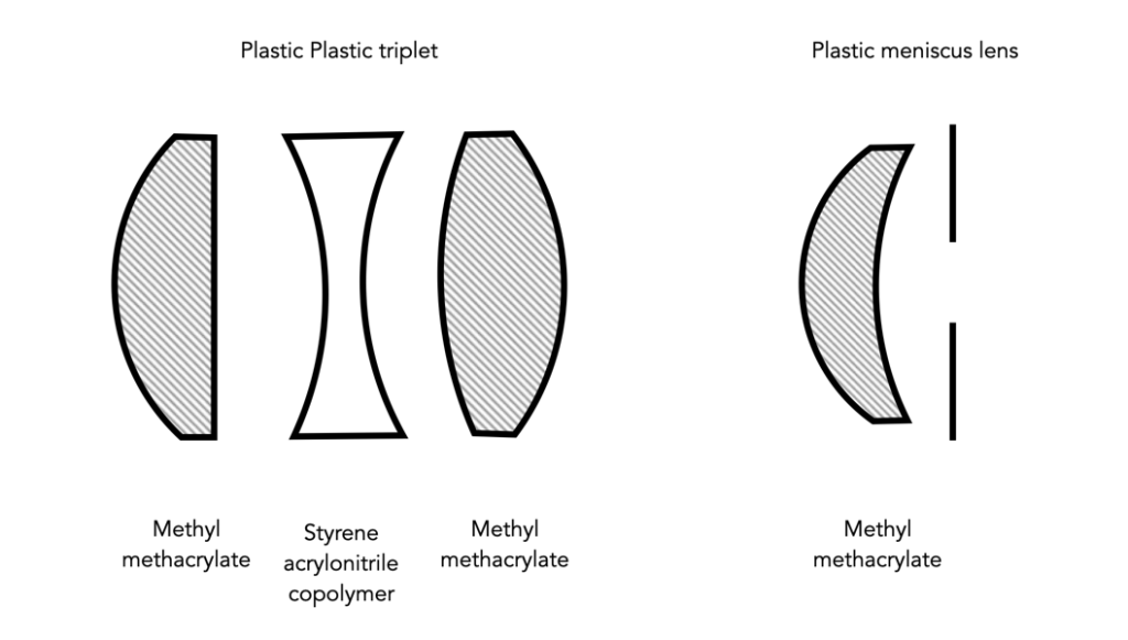
Plastic lenses are typically molded from polymers such as methyl methacrylate (MM), and styrene acrylonitrile copolymer (SAC). Optical glass is chemically nothing like optical grade plastic. Plastic has a definite molecular structure, whereas glass does not. Plastic is basically made from carbon, hydrogen and oxygen, whereas glass can contain a wide variety of materials, e.g. silicon dioxide, barium, boron, lead, and even thorium. The single biggest benefit of plastic is that it could be injection molded. Glass on the other hand, could not be injection molded as it would produce surface irregularities, which would then have to be ground and polished out (modern glass can be precision moulded). Injection molding allowed for complex shapes to be made easily, and inexpensively. Early plastic lenses suffered from something called “striation” whereby a lens has regions which with an index of refraction different from the rest of the lens, resulting in fuzzy pictures. It was caused by uneven cooling in the mold, but by the mid-60s this had been eliminated from lenses.

Plastics were said to suffer from defects, e.g. becoming pitted, or discoloured. However as they were usually used in simple, small lenses, this was hardly ever a real issue. Scratching (of the outer lens) was reduced through the use of plastics like Plexiglas V100, another acrylic which is very hard. The biggest issue with plastic lenses centred around the index of refraction (IR), which is a dimensionless number that indicates the light bending ability of a medium. The IR of plastics was (and is) rather low compared to optical glass. Acrylic has an IR of 1.49, and styrene acrylonitrile copolymer, 1.57. Compare this against modern glass of the period, at 1.52 to 1.89. Another problem was the fact that the IR of acrylics decreases as temperatures increases, changing the focus. Some plastic lenses were designed to automatically compensate for this. For example the plastic f/8 Cooke triplet, which used lens elements made from both acrylic and SAC. The focus of the acrylic elements (front and rear) increases, while the focus of the middle SAC lens decreases, balancing out any changes in focus.

The plastic lenses: Cooke triplet and the single lens

Lipton went a long way to describe the manufacturing benefits of plastic (and the drawbacks of optical glass) [4]. Optical glass is made by melting raw materials, which is processed when it cools into glass. Optical glass requires a number of steps including grinding, polishing, and testing, which made them expensive to manufacture. Plastic lenses on the other hand were simple to manufacture:

“Plastic lenses are made in air conditioned pressurized rooms, and in the case of Plexiglas or Lucite, the plastic, in powder form, is fed to a machine where it is heated and softened. It may be heated to a temperature of 400 to 500 degrees Fahrenheit. The softened plastic is then forced, under a pressure of at least 16,000 pounds per square inch, into a mold when it remains until it cools enough to retain the mold’s shape. The mold is then opened, and the lens is popped out, ready to be used as is, or assembled with other elements with no necessity for working to a finished size.”

Not that manufacturing optical plastics didn’t have its limitations. It was challenging to mold large diameter optical lenses, lenses with plane surfaces, and those with thick centres and thin edges. Lipton considered two stumbling blocks prohibiting the creation of high-speed 35mm lenses: low refractive indices, and the inability to mold large diameter lenses. In fact Dr. Rudolf Kingslake, director of optical design for Kodak, said of plastic objectives: “It’s the low indicies of refraction that are stopping us, it’s just a matter of substituting plastic for glass.”[4].

In 1972 Bob Schwalberg wrote an article describing why glass still reigned supreme [5]. He suggested SLR pentaprisms were a good candidate for conversion to acrylic which would reduce production costs. Schwalberg outlines five benefits:

  1. Lower cost – Raw materials are cheaper, and less expensive to work.
  2. Complete form freedom – Aspherical (non-spherical curvature) lenses are expensive to make in glass.
  3. Exceptional clarity – Not all optical glass is perfectly colourless, the highest grades of optical plastics are quite colourless, and their clarity frequently superior.
  4. Light weight – Plastic lenses are lighter.
  5. High impact resistance – Glass is brittle, plastics are flexible.

and five counter-arguments:

  1. Too limited range of optical specifications – i.e. The refractive index, and the dispersion. Refractive indexes for optical plastics are close to 1.5, optical glass ranges from 1.42 to 1.95.
  2. Poor curve holdability – Accurate lens curvatures are critical for quality performance. Plastic lenses have poor curve conformity because of (3) below, and their inherent flexibility. Glass is stronger and more stable, it holds curvature much better in the face of external forces.
  3. High temperature coefficients – The expansion and contraction of optical plastics is much greater than for optical glass. Muti-element plastic lenses have been developed with elements possessing opposing temperature coefficients. Unthinkable for precision camera lenses.
  4. Clear plastics are hygroscopic – They absorb airborne moisture. Optical media must be isotropic, i.e. equal in all directions. The absorption of moisture destroys this homogeneity.
  5. Low abrasion resistance – Plastics are softer and more prone to scratching than optical glass.
The Kodak Starmatic and its lens

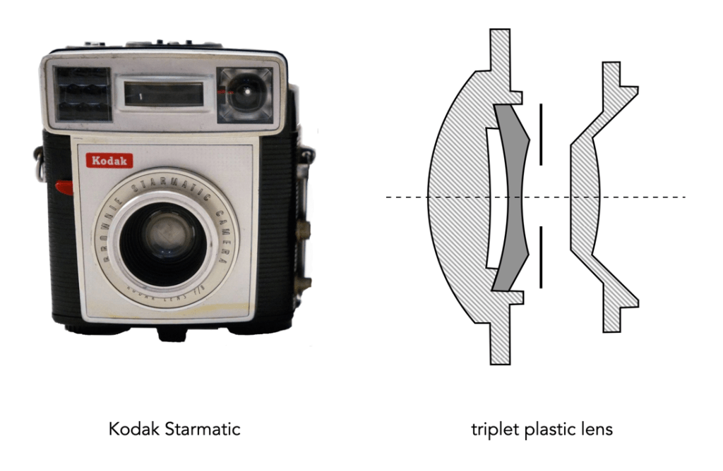
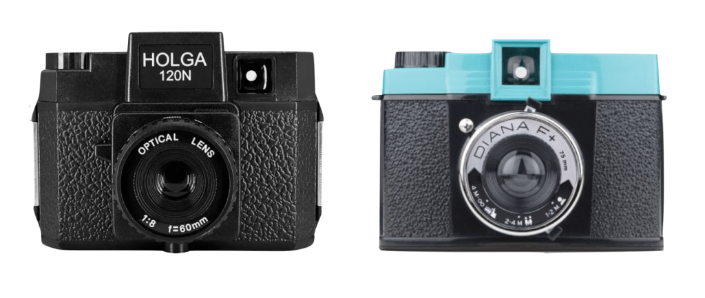
Many of the cameras that use(d) plastic lenses are considered to be “toy” cameras. In 1959 Kodak introduced the Starmatic, the top of Kodak’s Brownie line. It had an 44mm f/8 three-element, plastic lens. The Lomography Diana appearing in the 1960s, and was made entirely of plastic (and in 1975 cost less than $2). The Polaroid Pronto Land camera (mid 1970s), also had a 116mm 3-element Polatriplet plastic lens. Most Holga cameras, had a 60mm f/8 plastic meniscus lens.

But the breakthroughs and sophisticated designs associated with plastic lenses never really materialized. In the end, low refractive indices, and the inability to successfully mold large diameter lenses may have been stumbling blocks to making 35mm lenses from plastic. There are some plastic optical materials [6] that have reached a refractive index of as high as 1.68, e.g. PolyEtherImide, but they often suffer from having a lower transmission rate (36-82% for PolyEtherImide, versus 92% for acrylic). Leica APO glass, on the other hand, has a refractive index of 1.9005.

Apart from their use in inexpensive cameras, there is another use of optical plastic, that is in hybrid aspherics. A hybrid aspherical element is a lens element consisting of a glass base upon which plastic is glued, creating the desired aspheric shape. They are typically used in zoom lenses, e.g. the Nikon 28-70mm f/3.5-4.5 AF, first introduced in 1991. Companies like Tamron use hybrid aspherical lenses, likely to reduce the cost of the lenses. Lipton somewhat predicted this use in 1964 [4] when he suggested it would be difficult to grind an aspheric lens in optical glass, yet the manufacture of aspheric lenses in plastic would be no problem. Ironically, many smartphones have lenses which are actually plastic. This is not surprising considering the small size of the lenses required for mobile devices – it is less of a technological challenge, and hence costs less to manufacture (but as manufacturers don’t publish lens diagrams, it’s hard to know). For example the Leica lenses used in Huawei smartphones are plastic. Are there smartphones with glass elements? Sure, but they are usually quite expensive.

Ultimately the inability to derive high precision optics is one of the reasons we don’t see more plastic lenses. But there is another, human factor involved in companies shying away from the use of plastics – the perception of quality. Glass is more associated with quality that plastic, whereas plastic is considered “cheap”, and disposable. This is largely due to its use in inexpensive cameras, and the stigma attached to plastic itself.

  1. Andrew B. Hecht, “And Now Plastic Lenses”, Popular Photography, 18(5) pp.72-74,128 (1946)
  2. “Learn from Lenses”, Modern Plastics, 38(7), pp.90-93 (1961)
  3. Lloyd E. Varden, “Plastic Lenses”, Popular Photography, 49(2) p.48,97,98 (August, 1961)
  4. Leonard Lipton, “Plastic Lenses: Good Enough!”, Popular Photography, 55(2) p.44-45,100-101 (August, 1964)
  5. Bob Schwalberg, “Plastic optics vs. glass, and why glass still reigns”, Popular Photography, 70(2) p.52,118 (1972)
  6. Kingslake, R., Johnson, R.B., “The Work of the Lens Designer”, in Lens Design Fundamentals, 2nd ed. (2010)
  7. C.B.Estes, Thermally Compensated Plastic Triplet Lens, (July 24, 1961), Eastman Kodak Company, U.S. Patent No. 3,205,774

Further reading:

Rear Window – the 400mm lens

In a previous article, I discussed the Exakta VX camera used in Alfred Hitchcock’s “Rear Window”, suggesting that photojournalists of the period likely didn’t use super-telephoto lenses all that often (or at all). My view on this is based largely on articles I have read in magazines like Popular Photography during the 1950s.

The telephoto lens used by Jefferies in the movie is the Kilfitt Fern-Kilar f/5.6 400mm lens. The lens fits into the category of super-telephoto lenses with focal lengths in the range of 300-600mm. A number of manufacturers produced these lenses, although in all likelihood they had a narrow market. One of the earliest ads for Kilfitt lenses in Popular Photography appears in 1953, advertising their KILAR lenses for “medium and long tele shots” – it includes the 300mm and 400mm lenses. A review of the ads section of Popular Photography in 1954 reveals that the Kilfitt 400mm was being sold alongside the f/5.5 Hugo Meyer-Goerlitz Tele-Megor (which was the lens promoted by Exakta as well), and the Astro f/5.

The Kilfitt-Fern-Kilar 400mm f/5.6

Literature from Heinz Kilfitt Optische Fabrik suggests the lens could be used for “nature and expedition photography“, and also for “special press and feature assignments“. It is then likely that these long lenses were used in situations where a large kit could be carried. Some may argue that Jeff used the lens for sports photography, but that is unlikely, as many photojournalists tended to focus their careers on a particular genre of photography. For example Robert Capa, upon who Jefferies character is loosely based, worked predominantly in war zones: the Spanish Civil War, WWII, Palestine, and the war in Indochina (where he was killed by a landmine). In 1951 Bruce Downes wrote an article in Popular Photography, describing David Douglas Duncan’s photo coverage of the Korean War [2]. He photographed the carnage of war using two Leica IIIc’s, “practical combat cameras” that were “…light, compact and could stand a beating.”. From the perspective of lenses, he used Nikkor lenses: a 50mm f/1.5, a 85mm f/2 and a 135mm f/3.5. No large telephoto lenses in sight.

A steady telescope

In addition, even sports-photojournalists did not generally use long-tele lenses. Jesse Alexander (1929-2021), a motor-sports photographer, reportedly did not use long telephotos lenses. At the start of his career in early 1950s (his first photographic assignment was the 1953 La Carrera road race in Mexico), he used a Leica with 35mm and 135mm lenses, and a Rolleiflex for close-ups and portraits. I would suggest that the 400mm lens was either something Jefferies used occasionally, perhaps for some hobby photography, or merely something added to meet the needs of film. The only real evidence of Jefferies taking sports shots is the motor racing shot that ended up with Jefferies stuck in his apartment with a broken leg. The camera used there was a large format camera (most likely a Graflex), as evidenced by the photo hanging on the wall, taken in the middle of the racetrack.

Identifying the lens

The biggest elephant in the room with these telephoto lenses is their weight. The f/5.6 400mm lens weighed 62oz, or 1.76kg in weight. The faster Sport-Fern-Kilar f/4 400mm lens was even heavier, at 3.1kg. These lenses were just too heavy for a photojournalist to carry and use effectively in an active situation, e.g. a war zone. Even in everyday settings, the length of the telephoto would require the use of a tripod, otherwise shake will be greatly exaggerated – “A slight jiggle that would not be noticed if the scene were filmed with a standard lens will look like something shot on a pogo stick when you use a long telephoto lens.” [1]. It might be okay to use as a de facto telescope and prop up on your knee.

The interesting thing about Exakta is that their literature touted the idea of attaching a telephoto lens to a camera and turning it into a telescope – “a telescope that gives you long-range viewing with high magnification“. A 400mm telephoto lens would provide an eight-power photo-telescope.

NB: Sometimes it is speculated that the lens was actually an Astro-Berlin, a German company that made some pretty cool lenses, especially for the super-super telephoto (we’re talking 2000mm, f/10). These telephotos were often seen on Exakta cameras, hence the association.

  1. Herb A. Lightman, “Choosing and using lenses”, Popular Photography, 35(3), pp.107-117 (1954)
  2. Bruce Downes, “Assignment: Korea”, Popular Photography, 28(3), pp.42-51, March (1951)

the image histogram (vi) – contrast and clipping

Understanding shape and tonal characteristics is part of the picture, but there are some other things about exposure that can be garnered from a histogram that are related to these characteristics. Remember, a histogram is merely a guide. The best way to understand an image is to look at the image itself, not just the histogram.

Contrast

Contrast is the difference in brightness between elements of an image, and can determine how dull or crisp an image appears with respect to intensity values. Note that the contrast described here is luminance or tonal contrast, as opposed to colour contrast. Contrast is represented as a combination of the range of intensity values within an image and the difference between the maximum and minimum pixel values. A well contrasted image typically makes use of the entire gamut of n intensity values from 0..n-1.

Image contrast is often described in terms of low and high contrast. If the difference between the lightest and darkest regions of an image is broad, e.g. if the highlights are bright, and the shadows very dark, then the image is high contrast. If an image’s tonal range is based more on gray tones, then the image is considered to have a low contrast. In between there are infinite combinations, and histograms where there is no distinguishable pattern. Figure 1 shows an example of low and high contrast on a grayscale image.

Fig.1: Examples of differing types of tonal contrast

The histogram of a high contrast image will have bright whites, dark blacks, and a good amount of mid-tones. It can often be identified by edges that appear very distinct. A low-contrast image has little in the way of tonal contrast. It will have a lot of regions that should be white but are off-white, and black regions that are gray. A low contrast image often has a histogram that appears as a compact band of intensities, with other intensity regions completely unoccupied. Low contrast images often exist in the midtones, but can also appear biased to the shadows or highlights. Figure 2 shows images with low and high contrast, and one which sits midway between the two.

Fig.2: Examples of low, medium, and high contrast in colour images

Sometimes an image will exhibit a global contrast which is different to the contrast found in different regions within the image. The example in Figure 3 shows the lack of contrast in an aerial photograph. The image histogram shows an image with medium contrast, yet if the image were divided into two sub-images, both would exhibit low-contrast.

Fig.3: Global contrast versus regional contrast

Clipping

A digital sensor is much more limited than the human eye in its ability to gather information from a scene that contains both very bright, and very dark regions, i.e. a broad dynamic range. A camera may try to create an image that is exposed to the widest possible range of lights and darks in a scene. Because of limited dynamic range, a sensor might leave the image with pitch-black shadows, or pure white highlights. This may signify that the image contains clipping.

Clipping represents the loss of data from that region of the image. For example a spike on the very left edge of a histogram may suggest the image contains some shadow clipping. Conversely, a spike on the very right edge suggests highlight clipping. Clipping means that the full extent of tonal data is not present in an image (or in actually was never acquired). Highlight clipping occurs when exposure is pushed a little too far, e.g. outdoor scenes where the sky is overcast – the white clouds can become overexposed. Similarly, shadow clipping means a region in an image is underexposed,

In regions that suffer from clipping, it is very hard to recover information.

Fig.4: Shadow versus highlight clipping

Some describe the idea of clipping as “hitting the edge of the histogram, and climbing vertically”. In reality, not all histograms exhibiting this tonal cliff may be bad images. For example images taken against a pure white background are purposely exposed to produce these effects. Examples of images with and without clipping are shown in Figure 5.

Fig.5: Not all edge spikes in a histogram are clipping

Are both forms of clipping equally bad, or is one worse than the other? From experience, highlight clipping is far worse. That is because it is often possible to recover at least some detail from shadow clipping. On the other hand, no amount of post-processing will pull details from regions of highlight-clipping in an image.

the image histogram (v) – tone

In addition to shape, a histogram can be described using different tonal regions. The left side of the histogram represents the darker tones, or shadows, whereas the right side represents the brighter tones, or highlights, and the middle section represents the midtones. Many different examples of histograms displaying these tonal regions exist. Figure 1 shows a simplified version containing 16 different regions. This is somewhat easier to visualize than a continuous band of 256 grayscale values. The histogram depicts the movement from complete darkness to complete light.

Fig.1: An example of a tonal range – 4-bit (0-15 gray levels)e

The tonal regions within a histogram can be described as:

  • highlights – The areas of a image which contain high luminance values yet still contain discernable detail. A highlight might be specular (a mirror-like reflection on a polished surface), or diffuse (a refection on a dull surface).
  • mid tones – A midtone is an area of an image that is intermediate between the highlights and the shadows. The areas of the image where the intensity values are neither very dark, nor very light. Mid-tones ensure a good amount of tonal information is contained in an image.
  • shadows – The opposite of highlights. Areas that are dark but still retain a certain level of detail.

Like the idealized view of the histogram shape, there can also be a perception of an idealized tonal region – the midtones. However an image containing only midtones tends to lack contrast. In addition, some interpretations of histograms add additional an additional tonal category at either extreme. Both can contribute to clipping.

  • blacks – Regions of an image that have near-zero luminance. Completely black areas are a dark abyss.
  • whites – Regions of an image where the brightness has been increased to the extent that highlights become “blown out”, i.e. completely white, and therefore lack detail.

Figure 2 shows an image which illustrates nearly all the regions (with a very weird histogram). The numbers on the image indicate where in the histogram those intensities exist. The peak at ① shows the darkest regions of the image, i.e. the deepest shadows. Next, the regions associated with ② include some shadow (ironically they are in shadow), graduating to midtones. The true mid-tonal region, ③, are regions of the buildings in sunlight. The highlights, ④, are almost completely attributed to the sky, and finally there is a “white” region, ⑤, signifying a region of blow-out, i.e. where the sun is reflecting off the white-washed parts of the building.

Fig.2: An example of the various tonal regions in an image histogram

Figure 3 shows how tonal regions in a histogram are associated with pixels in the image. This image has a bimodal histogram, with the majority of pixels in one of two humps. The dominant hump to the left, indicates a good portion of the image is in the shadows. The right-sided smaller hump is associated with the highlights, i.e. the sky, and sunlit pavement. There is very little in the way of midtones, which is not surprising considering the harsh lighting in the scene.

Fig.3: Tonal regions associated with image regions.

Two other commonly used terms are low-key and high-key.

  • A high-key image is one composed primarily of light tones, and whose histogram is biased towards 255. Although exposure and lightning can influence the effect, a light-toned subject is almost essential. High-key pictures usually have a pure or nearly pure white background, for example scenes with bright sunlight or a snowy landscape. The high-key effect requires tonal graduations, or shadows, but precludes extremely dark shadows.
  • A low-key image describes one composed primarily of dark tones, where the bias is towards 0. Subject matter, exposure and lighting contribute to the effect. A dark-toned subject in a dark-toned scene will not necessarily be low-key if the lighting does not produce large areas of shadow. An image taken at night is a good example of a low-key image.

Examples are shown in Figure 4.

Fig.4: Examples of low-key and high-key images.

Why did 35mm photography become so popular?

Everything in modern digital photography seems to hark back to analogue 35mm. The concept of “full-frame” only exists because a full frame sensor is equivalent in size to the 24×36mm frame of 35mm film (which was only called 35mm because that was the width of the film). If we didn’t have this association, there would be no crop-sensor. Most early films for cameras were quite large format – introduced in 1899, 116 format film was 70mm wide. This was followed in 1901 by 120 (60mm), 127 (40mm) in 1912, and then 620 (60mm) in 1931. So there were certainly many film format options. So why did 35mm become the standard?

In all likelihood, 35mm became the gold standard because of how widely available 35mm film was in the motion picture industry – it had been around since 1889 when Thomas Edison’s assistant, William Kennedy Dickson simply split 70mm Eastman Kodak film in half. (I have discussed the origins of 35mm film in a previous post). Kodak introduced the standard 135 film in 1934, and was designed for making static pictures (rather than film) with the actual exposure frames being 36mm wide, and 24mm high, giving it a 3:2 ratio. In the 1930s, Leica brochures expounded the fact that the film used in their cameras was “…the standard 35mm cinema film stock, obtainable all over the world.

A standard Leica with a 50mm f/3.5 ELMAR lens

There was much hype in the 1930s about the cameras that were termed “minicams”, or “candid cameras”, in effect cameras that used 35mm film. By the mid 1930s, Leica had been producing 35mm cameras for over a decade. A 1936 Fortune Magazine article titled “The U.S. Minicam Boom” described the Leica as a camera which “took thirty-six pictures the size of the special-delivery stamp on a roll of movie film.” There were those who did not think the miniature camera would survive, seeing their use as a form of candid camera craze. Take for example the closing argument of Thomas Uzzell, who wrote the negative perspective of a 1937 article “Will the Miniature Survive the Candid Camera Craze?” [1]:

“The little German optical jewels you carry in your (sagging) coat pockets make many experimental exposures expensive (though perhaps they would do better if they carefully made one good one!). Their shorter focal lengths make the ultra-fast exposures more practical (how many pictures are actually taken at these ultra speeds!). You can hop about quickly, minnie in hand, and take photos of children and babies at play with all the detail that “makes a picture pulse with naturalness and life” (though good pictures have never been taken by anyone hoping about). … I claim there is just one thing they cannot do, and apparently are never going to be able to do. They can’t make clear pictures.”

Uzzell claimed the art of the miniature was the art of the fuzzy picture. His challenger, Homer Jensen on the other hand described the inherent merits of 35mm over larger format cameras, namely that one could “…take pictures under the most unfavourable conditions, indoors and outdoors.”. Some people disliked the minicam because it made it too easy to take pictures (like anyone could take pictures).

One of the reasons 35mm was so successful was the small size of the camera itself. Their lightweight nature made them easy to carry, taking up very little room. This made them popular with both causal photographers and professionals such as photojournalists where the use of bulky equipment would be prohibitive. Another reason was the 35mm camera’s ability to work in existing light conditions. This was an affect of having ultra-fast lenses, something the larger format cameras could not practically achieve. The shorter focal lengths of 35mm cameras also allowed for greater depth-of-field at wide lens apertures. The inaugural issue of Popular Photography in 1937 described the advantages of using miniatures to capture fast action [4].

A large format Graflex camera versus a Leica “minicam”.

Large format cameras on the other hand, were sometimes referred to as “Big Berthas” due to their size [4]. The Series D Graflex, a quintessential 4×5″ press camera of the 1930s weighed 3.06kg, compared with the Leica G, which was one-sixth its weight, and roughly 1/30th its size. In a Graflex brochure from 1936, photographer H. Armstrong Roberts recalls a recent 14,000 mile journey where he took 3000 negatives using his Graflex camera, stating that “Certain I am that no other camera could have achieved the results which I have obtained with the GRAFLEX.”

In 1935, another event foreshadowed the success of 35mm photography – Kodak’s introduction of Kodachrome colour film, followed shortly afterwards by Agfa’s Agfacolor Neu. This may have persuaded many a professional photographer to move to 35mm. Indeed, by 1938, H. Armstrong Roberts was also shooting in colour using a Zeiss Contaflex with a 50mm f/2 Sonnar lens [5] (so much for his belief in large format). The onset of WW2 brought a halt to the first minicam boom, but it was not the end of the story. By the early 1950s, the minicam was on the cusp of greatness, soon to become the standard means of taking photographs. More articles started to appear in photography magazines, enunciating the virtues of 35mm [3].

There are many reasons 35mm film became the format of choice.

  • Kodak’s 135 film single-use cartridge allowed for daylight loading. Prior to this 35mm film had to be loaded onto reusable cassettes in the darkroom.
  • The physical format of 35mm film made it very user friendly. The film is contained in a metal canister that reduces the risk of light leaks, and is easy to handle. Loading/unloading film is both intuitive, quick and easy. It’s compact size made it much easier to handle than larger format film.
  • 35mm also allowed for more exposures per roll than typical large format films. The norm is 24 or 36 exposures. This provided a great deal of flexibility in the amount of shots that could be taken, because 35mm film was easier and cheaper to develop.
  • In the hey-day of film photography there was a huge selection of film types – B&W, colour, infrared, and slide.

Of course there were also some limitations, but these mostly centre on the fact that 35mm film was considered to have less resolving power than medium-format film – great for “snapshots”, but anyone that required large prints needed a large film format to avoid grainy prints.

The invention of the Leica started a new era in photography, spurned on by the introduction of Kodak’s 135 film. Post WW2, 35mm film spearheaded the photographic revolution of the 1950s. It became the format used by amateurs, hobbyists, and professionals alike. 35mm photography allowed for a light, yet flexible kit, which was ideal for the travelling amateur photographer of the 1960s.

Further reading:

  1. Uzzell, Thomas, H., “Will the Miniature Survive the Candid Camera Craze? – No”, Popular Photography, 1(4), pp. 32,66 (1937)
  2. Jensen, Homer, “Will the Miniature Survive the Candid Camera Craze? – Yes”, Popular Photography, 1(4), pp. 33,84 (1937)
  3. “35mm: The camera and how to use it”, Popular Photography, pp.50-54,118, November (1951)
  4. Witwer, Stan, “Fast Action with a Miniature”, Popular Photography, 1(1) pp.19-20,66 (1937)
  5. “Taking the May Cover in Color”, Popular Photography, 2(5) pp.54 (1938)

The human visual system : focus and acuity

There is a third difference between cameras and the human visual system (HVS). While some camera lenses may share a similar perspective of the world with the HVS with respect to the angle-of view, where they differ is what is actually in the area of focus. Using any lens on a camera means that a picture will have an area where the scene is in-focus, with the remainder being out-of-focus. This in-focus region generally occurs in a plane, and is associated with the depth-of-field. On the other hand, the in-focus region of the picture our mind presents us does not have a plane of focus.

While binocular vision allows approximately 120° of (horizontal) vision, it is only highly focused in the very centre, with the remaining picture being increasingly out-of-focus depending on how far a point is away from the central focused region. This may be challenging to visualize, but if you look at an object, only the central point is in focus, the remainder of the picture is out-of-focus. That does not mean it is necessarily blurred, because the brain is still able to discern shape and colour, just not fine details. Blurring it usually a function of distance from the object being focused on, i.e. the point-of-focus. If you look at a close object, distant objects will be out-of-focus, and vice versa.

Fig.1: Parts of the macula

Focused vision is related to the different parts of the macula, an oval-shaped pigmented area in the centre of the retina which is responsible for interpreting vision, colour, fine details, and symbols (see Figure 1). It is composed almost entirely of cones, into a series of zones:

  • perifovea (5.5mm∅, 18°) : Details that appear in up to 9-10° of visual angle.
  • parafovea (3mm∅, 8°) : Details that appear in peripheral vision, not as sharp as the fovea.
  • fovea (1.5mm∅, 5°) : Or Fovea centralis, comprised entirely of cones, and responsible for high-acuity, and colour vision.
  • foveola (0.35mm∅, 1°) : A central pit within the fovea, which contains densely packed cones. Within the foveola is a small depression known as the umbo (0.15mm∅), which is the microscopic centre of the foveola.
Fig.2: Angle-of-view of the whole macula region, versus the foveola. The foveola provides the greatest region of acuity, i.e. fine details.

When we fixate on an object, we bring an image of that object onto the fovea. The foveola provides the greatest amount of visual acuity, in the area 1-2° outwards from the point of fixation. As the distance from fixation increases, visual acuity decreases quite rapidly. To illustrate this effect, try reading the preceding text in this paragraph while fixating on the period at the end of the sentence. It is likely challenging, if not impossible, to read text outside a small circle of focus from the point of fixation. A seven letter word, like “outside”, is about 1cm wide, which when read on a screen 60cm from your eye represents about an angle of 1°. The 5° of the fovea region allows for a “preview” of the words either side, and parafovea region, 8° of peripheral words (i.e. their shape). This is illustrated in Figure 3.

Fig.3: Reading text from 60cm

To illustrate how this differential focus affects how humans view a scene, consider the image shown in Figure 4. The point of focus is a building in the background roughly 85m from where the person is standing. This image has been modified by adding radial blur from a central point-of-focus to simulate in-focus versus out-of-focus regions as seen by the eye (the blur has been exaggerated). The sharpest region is the point of fixation in the centre – from this focus on a particular object, anything either side of that object will be unsharp, and the further away from that point, the more unsharp is becomes. The

Fig.4: A simulation of focused versus out-of-focus regions in the HVS (the point of fixation is roughly 85m from the eyes)

It is hard to effectively illustrate exactly how the HVS perceives a scene as there is no way of taking a snapshot and analyzing it. However we do know that focus is a function of distance from the point-of-focus. Other parts of an image as essentially de-emphasized, there is still information there, and the way our minds process it, it provides a complete vision, but there is a central point of focus.

Further reading:

  1. Ruch, T.C., “Chapter 21: Binocular Vision, and Central Visual Pathways”, in Neurophysiology (Ruch, T.C. et al. (eds)) p.441-464 (1965)

the image histogram (iv) – shape

One of the most important characteristics of a histogram is its shape. A histogram’s shape offers a good indicator of an image’s ability to tolerate manipulation. A histogram shape can help elucidate the overall contrast in the image. For example a broad histogram usually reflects a scene with significant contrast, whereas a narrow histogram reflects less contrast, with an image which may appear dull or flat. As mentioned previously, some people believe an “ideal” histogram is one having a shape like a hill, mountain, or bell. The reality is that there are as many shapes as there are images. Remember, a histogram represents the pixels in an image, not their position. This means that it is possible to have a number of images that look very different, but have similar histograms.

The shape of a histogram is usually described in terms of simple shape features. These shape features are often described using geographical terms (because a histogram often reminds people of the profile view of a geographical feature): e.g. “hillock” or “mound”, which is a shallow, low feature, “hill” or “hump”, which is a feature rising higher than the surrounding areas, a “peak”, which is a feature with a distinctly top, a “valley”, which is a low area between two peaks, or a “plateau” which is a level region between other features. Features can either be distinct, i.e. recognizably different, or indistinct, i.e. not clearly defined, often blended with other features. These terms are often used when describing the shape of a particular histogram in detail.

Fig.1: A sample of feature shapes in a histogram

From the perspective of simplicity, however histogram shapes can be broadly classified into three basic categories (examples are shown in Fig.2):

  • Unimodal – A histogram where there is one distinct feature, typically a hump or peak, i.e. a good amount of an image’s pixels are associated with the feature. The feature can exist anywhere in the histogram. A good example of a unimodal histogram is the classic “bell-shaped” curve with a prominent ‘mound’ in the center and similar tapering to the left and right (e.g. Fig.2: ①).
  • Bimodal – A histogram where there are two distinct features. Bimodal features can exist as a number of varied shapes, for example the features could be very close, or at opposite ends of the histogram.
  • Multipeak – A histogram with many prominent features, sometimes referred to as multimodal. These histograms tend to differ vastly in their appearance. The peaks in a multipeak histogram can themselves be composed of unimodal or bimodal features.

These categories can can be used in combination with some qualifiers (numeric examples refer to Figure 2). For example a symmetric histogram, is a histogram where each half is the same. Conversely an asymmetric histogram is one which is not symmetric, typically skewed to one side. One can therefore have a unimodal, asymmetric histogram, e.g. ⑥ which shows a classic “J” shape. Bimodal histograms can also be asymmetric (⑪) or symmetric (⑬).

Fig.2: Core categories of histograms: unimodal, bimodal, multi-peak and other.

Histograms can also be qualified as being indistinct, meaning that it is hard to categorize it as any one shape. In ㉓ there is a peak to the right end of the histogram, however the major of the pixels are distributed in the uniform plateau to the right. Sometimes histogram shapes can also be quite uniform, with no distinct groups of pixels, such as in example ㉒ (in reality though these images are quite rare). It it also possible that the histogram exhibits quite a random pattern, which might only indicate quite a complex scene.

But a histogram’s shape is just its shape. To interpet a histogram requires understanding the shape in context to the contents of the scene within the image. For example, one cannot determine an image is too dark from a left-skewed unimodal histogram without knowledge of what the scene entails. Figure 3 shows some sample colour images and their corresponding histograms, illustrating the variation existing in histograms.

Fig.3: Various colour images and their corresponding intensity histograms

The human visual system : image shape and binocular vision

There are a number of fundamental differences between a “normal” 50mm lens and the human visual system (HVS). Firstly, a camera extracts a rectangular image from the circular view of the lens. The HVS on the other hand is not circular, nor rectangular – if anything it has somewhat of an oval shape. This can be seen in the diagram of binocular field of vision shown in Figure 1 (from [1]). The central shaded region is the field of vision seen by both eyes, i.e. binocular (stereoscopic) vision, the white areas on both sides are the monocular crescents, seen by only by each eye, and the blackened area is not seen.

Fig.1: One of the original diagrams illustrating both the shape of vision, and the extent of binocular vision [1].

Figure 1 illustrates a second difference, the fact that normal human vision is largely binocular, i.e. uses both eyes to produce an image, whereas most cameras are monocular. Figure 2 illustrates binocular vision more clearly, comparing it to the total visual field.

Fig.2: Shape and angle-of-view, total versus binocular vision (horizontal).

The total visual field of the HVS is 190-200° horizontally, which is composed of 120° of binocular vision, and two fields of 35-40° seen by one one eye. Vertically, the visual field of view is about 130° (and the binocular field is roughly the same), comprised of 50° above the horizontal line-of-sight, and 70-80° below it. An example to illustrate binocular vision (horizontal) is shown in Figure 3.

Fig.3: A binocular (horizontal – 120°) view of Bergen, Norway

It is actually quite challenging to provide an exact example of what a human sees – largely because trying to take the same picture would require a lens such as a fish-eye which would introduce distortions, something the HVS is capable of filtering out.

Further reading:

  1. Ruch, T.C., “Chapter 21: Binocular Vision, and Central Visual Pathways”, in Neurophysiology (Ruch, T.C. et al. (eds)) p.441-464 (1965)

The glass beans – the origin of “lens”

When lenses first appeared they had a particular shape, a double convex lens, that was very similar to a certain pulse, namely the lentil. The name lens derived from the Latin name for the plant, lens culinaris.

“LENS (Latin , lens, a small bean or lentil). A lens is a piece of transparent material (usually glass) bounded by curved surfaces (generally spherical, including flat).

A.L.M. Sowerby’s Dictionary of Photography (1951) p.407

An English dictionary of the early 18th century [1] describes a lens as related to optics to be a “small concave or convex glass”. By 1768 [2] it was described as “a glass, spherically convex on both sides”.

The word lentil comes from the Old French lentille, which in turn comes from Latin lenticula. When lenses first appeared, they looked like the lentil seed, and likely due to the fact that technical terms were derived from Greek or Latin, simply named them lens. In German, one term used is Linse, but it is more common to use the term Objektiv. The term Linse is from the Old High German linsa, from a Proto-Indo-European root.

  1. Dictionarium Anglo-Britannicum, John Kersey (1708)
  2. A Dictionary of the English Language, Samuel Johnson (1768)

Why was the 50mm lens considered “normal”?

Why was the 50mm lens considered the “normal” lens used on 35mm cameras? Why not 40mm or 60mm? When Barnack introduced his revolutionary Leica camera, he used a traditional method of selecting the lens – the most commonly used lens has a focal length should be approximately equal to the diagonal of the negative, which is how the 50mm likely evolved. The Leica I came with a fixed 50mm lens, and even when the Leica II appeared in 1932 with interchangeable lenses, the viewfinder was designed to work with 50mm lenses. Zeiss Contax lens brochures from the 1930s mark 50mm lenses as “universal lenses”, “For all-round use and subjects which occur in every-day photography…”. Nikon also made the point that “Nikkor normal lenses cover a picture angle of approximately 45°, corresponding closely to the angle of view of the human eye”.

It is then no surprise that 50mm is the most ubiquitous analog lens. By the 1950s, most interchangeable lens cameras came standard with a 50mm lens, ensuring that novice photographers could capture sharp photographs in a variety of conditions without requiring a books worth of knowledge. Nikon in one of their lens brochures suggested “the 50mm focal length has become the standard lens for all around work”. This deep-seeded ideology is probably why 50mm lenses came in so many speeds – the same Nikon brochure provides an f/3.5, f/2, f/1.4, and f/1.1 50mm lenses. Many camera manufacturers followed suit. The late 1970s “standard” line-up for Asahi Pentax included four 50mm lenses (f/1.2, f/1.4, f/1.7, f/2) and a 40mm f/2.8 which they touted as being “extremely versatile”.

Fig.1: How many normal’s is too many normal’s? (Pentax SMC lenses)

There are a number of arguments that have traditionally been made as to why 50mm is “normal”. The most common argument of course is that the 50mm lens has a diagonal angle-of-view (AOV) of about 45° which approximates the AOV of the human eye. But in reality it makes assumptions about what “normal vision” is , and the ability of a 50mm lens to reproduce it. The idea that 50mm best approximates human vision has more to do with the evolution of lenses than it has to do with any correspondence between the human eye and a lens. There are other arguments, for instance that 50mm reproduces facial proportions, depth and perspective roughly as how our eyes perceive them. Many manufacturers drove this point home by saying 50mm lenses “give pictures of natural, i.e. normal, perspective”.

Fig.2: Angle of views of the human vision system

Firstly we should remember that “normal” human vision is binocular, while camera lenses are not. The eye is also composed of a gel-like material, versus the glass of lens elements. So there are already fundamental structural and functional differences. There is also the matter of AOV. A lens generally has one AOV, whereas the human visual system (HVS) has a series, based on differing abilities to focus – binocular vision is approximately 120° of view, of which only 60° is the central field of vision (the remainder is peripheral vision), and only 30° of that is vision capable of symbol recognition (even less is capable of sharp focusing, perhaps 5°?). Note that I use horizontal AOV in comparisons, because it is easier for people to conceptualize than diagonal AOV.

Fig.3: AOV of various lens focal lengths against the AOV of the human vision system

In reference to Figure 3, for the hard limits, a 67mm lens would likely best approximate the 30° region of the HVS that deals with symbol recognition, whereas a 31mm would best approximate the 60° central field of vision. If we were simply to take the middle ground, at 45°, we get a 43mm lens, which actually matches the diagonal of the 24×36mm frame.

But how closely does the 50mm AOV resembles that of the human visual system (HVS)? In terms of horizontal vision, a 50mm lens has a 40° AOV, so it’s not that far removed from that of the 43mm lens. Part of the problem lies with the fact that it is hard to establish an exact value that represents the “normal viewing angle” of the HVS. This is why other lens fit into this “normal” category – the 40mm (48°), the 45mm (44°), the 55mm (36°) and the 58mm (34°). Herbert Keppler may have put it best in his book The Asahi Pentax Way (1966):

“A normal focal length lens on any camera is considered to be a lens whose focal length closely approximates the diagonal of the picture area produced on the film. With 35mm cameras, this actually works out to be about 43mm, generally considered a little too short to produce the best angle of coverage and most pleasing perspective. Consequently, makers of 35mm cameras have varied their “normal” focal lengths between 50 and 58mm. With early single lens reflexes the longer 58mm length was in general use. However, in recent years there seems to be a trend to slightly shorter focal lengths which produce a greater angle of view. Current Pentax models use both 50 and 55mm focal length lenses.”

In some respects it seems like 50mm was chosen because it is close to what could be perceived as the AOV of the HVS, such that it is, and provided a nice rounded focal length value. By the 1950s, the 50mm had become “the standard” lens, with 35mm and 85mm lenses providing wide and telephoto capabilities respectively (a 35mm lens has an AOV of 54°, and the 85mm lens has an AOV of 24°, and surprisingly, 50mm sits smack dab in the middle of these). Many brochures simply identified it as an “all-round” lens. It is difficult to pinpoint where the reference of 50mm approximating the AOV of the human eye may have first appeared.

With the move to digital, the exact notion of a 50mm “normal” lens has not exactly persevered. This is primarily because the industry has moved away from 36×24mm being the normal film/sensor size, even though we hang onto the idea of 35mm equivalency. While a 50mm lens might be considered “normal” on a full-frame sensor, on an APS-C sensor a “normal” lens would be 35mm, because it is “equivalent” to a 50mm full-frame lens, from the perspective of focal length and more importantly AOV. Note that Zeiss still allude to the fact that the “focal length of the ZEISS Planar T* 1.4/50 is equal to the perspective of the human eye.”