Things to consider when choosing a digital camera

There is always a lot to think about when on the path to purchasing a new camera. In fact it may be one of the most challenging parts of getting started in photography, apart from choosing which lenses will be in your kit. It was frankly easier when there was less in the way of choices. You could make a list of 100 different things with which to compare cameras, but better to start with a simple series of things to consider.

Some people are likely swayed by fancy advertising, or cool features. Others think only of megapixels. There are of course many things to consider. This post aims to provide a simple insight into the sort of things you should consider when buying a digital camera. It is aimed at the pictorialist, or hobby/travel photographer. The first thing people think about when considering a camera is megapixels. These are important from a marketing perspective, mainly because they are a quantifiable number that can be sold to potential buyers. It is much harder to sell ISO or dynamic range. But megapixels aren’t everything, as I mentioned in a previous post, anywhere from 16-24 megapixels is fine. So if we move beyond the need for megapixels, what should we look for in a camera?

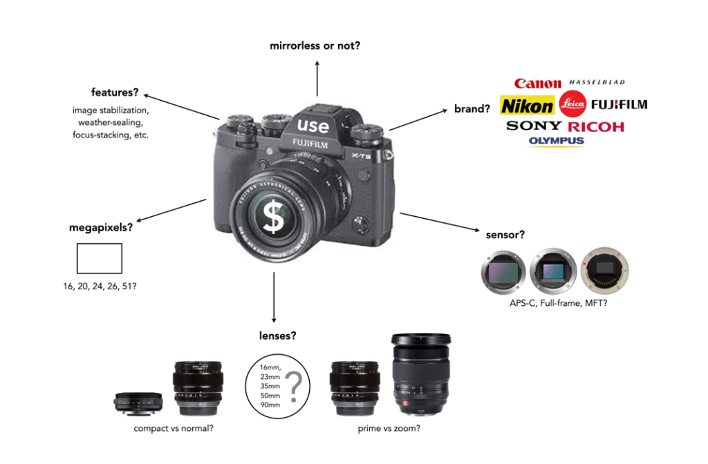
Perhaps the core requirement for a non-professional photographer is an understanding of what the camera is to be used for – landscapes, street photography, macro shooting, travel, blogging, video? This plays a large role in determining the type of camera from the perspective of the sensor. Full frame (FF) cameras are only required by the most dedicated of amateur photographers. For everyday shooting they can be far too bulky and heavy. At the other end of the spectrum is Micro-Four-Thirds (MFT), which is great for travelling because of it is compact size. In the middle are the cameras with APS-C sensors, sometimes often found in mirrorless cameras, and even compact fixed-lens format cameras. If you predominantly make videos, then a camera geared towards maybe less MP and more video features is essential. For street photography, perhaps something compact and unobtrusive. Many people also travel with a back-up camera, so there is that to consider as well.

Next is price, because obviously if I could afford it I would love a Leica… but in the real world it’s hard to justify. As the sensor gets larger, the price goes up accordingly. Large sensors cost more to make, and mechanisms such as image stabilization have to be scaled accordingly. Lenses for FF are also more expensive because they contain larger pieces of glass. It’s all relative – spend what you feel comfortable spending. It’s also about lifespan – how long will you use this camera? It was once about upgrading for more megapixels or fancy new features – it’s less about that now. Good cameras aren’t cheap – nothing in life is, neither are good lenses… but spend more for better quality and buy fewer lenses.

Then there are lenses. You don’t need dozens of them. Look at what lenses there are for what you want to do. You don’t need a macro lens if you are never going to take closeup shots, and fisheye lenses are in reality not very practical. Zoom lenses are the standard lenses supplied with many cameras, but the reality is a 24-80 is practical (although you honestly won’t use the telephoto function that much), anything beyond 80mm is likely not needed. Choose a good quality all round prime lens. There are also a variety of price points with lenses. Cheaper lenses will work fine but may not be as optically nice, have weather proofing or contain plastic instead of metal bodies. You can also go the vintage lens route – lots of inexpensive lenses to play with.

Now we get to the real Pandora’s Box – features. What extra features do you want? Are they features that you will use a lot? Focus stacking perhaps, for well focused macro shots. Manual focus helpers like focus peaking for use with manual lenses. High resolution mode? Image stabilization (IS)? I would definitely recommend IS but lean perhaps towards the in-body rather than the in-lens. In body means any lens will work with IS, even vintage ones. In lens is just too specialized and I favour less tech inside lenses. Features usually come at a price- battery drain, so think carefully about what makes sense for your particular situation.

So what to choose? Ultimately you can read dozens of reviews, watch reviews on YouTube, but you have to make the decision. If you’re unsure, try renting one for a weekend and try it out. There is no definitive guide to buying a digital camera, because there is so much to choose from, and everyone’s needs are so different.

The basics of the X-Trans sensor filter

Many digital cameras use the Bayer filter as a means of capturing colour information at the photosite level. Bayer filters have colour filters which repeat in 2×2 pattern. Some companies, like Fuji use a different type of filter, in Fuji’s case the X-Trans filter. The X-Trans filter appeared in 2012 with the debut of the Fuji X-Pro1.

The problem with regularly repeating patterns of coloured pixels is that they can result in moiré patterns when the photograph contains fine details. This is normally avoided by adding an optical low-pass filter in front of the sensor. This has the affect of applying a controlled blur on the image, so sharp edges and abrupt colour changes and tonal transitions won’t cause problems. This process makes the moiré patterns disappear, but at the expense of some image sharpness. In many modern cameras the sensor resolution often outstrips the resolving power of lenses, so the lens itself acts as a low-pass filter, and so the LP filter has been dispensed with.

Bayer (left) versus X-Trans colour filter arrays

C-Trans uses a more complex array of colour filters. Rather than the 2×2 RGBG Bayer pattern, the X-Trans colour filter uses a larger 6×6 array, comprised of differing 3×3 patterns. Each pattern has 55% green, 22.5% blue and 22.5% red light sensitive photosite elements. The main reason for this pattern was to eliminate the need for a low-pass filter, because this patterning reduces moiré. This theoretically strikes a balance between the presence of moiré patterns, and image sharpness.

The X-Trans filter provides a for better colour production, boosts sharpness, and reduces colour noise at high ISO. On the other hand, more processing power is needed to process the images. Some people say it even has a more pleasing “film-like” grain.

CharacteristicX-TransBayer
Pattern6×6 allows for more organic colour reproduction.2×2 results in more false-colour artifacts.
MoiréPattern makes images less susceptible to moiré.Bayer filters contribute to moiré.
Optical filterNo low-pass filer = higher resolution.Low-pass filter compromises image sharpness.
ProcessingMore complex to process.Less complex to process.
Pros and Cons between X-Trans and Bayer filters.

Further reading:

How does high-resolution mode work?

One of the tricks of modern digital cameras is a little thing called “high-resolution mode” (HRM), which is sometimes called pixel-shift. It effectively boosts the resolution of an image, even though the number of pixels used by the camera’s sensor does not change. It can boost a 24 megapixel image into a 96 megapixel image, enabling a camera to create images at a much higher resolution than its sensor would normally be able to produce.

So how does this work?

In normal mode, using a colour filter array like Bayer, each photosite acquires one particular colour, and the final colour of each pixel in an image is achieved by means of demosaicing. The basic mechanism for HRM works through sensor-shifting (or pixel-shifting) i.e. taking a series of exposures and processing the data from the photosite array to generate a single image.

  1. An exposure is obtained with the sensor in its original position. The exposure provides the first of the RGB components for the pixel in the final image.
  2. The sensor is moved by one photosite unit in one of the four principal directions. At each original array location there is now another photosite with a different colour filter. A second exposure is made, providing the second of the components for the final pixel.
  3. Step 2 is repeated two more times, in a square movement pattern. The result is that there are four pieces of colour data for every array location: one red, one blue, and two greens.
  4. An image is generated with each RGB pixel derived from the data, the green information is derived by averaging the two green values.

No interpolation is required, and hence no demosaicing.

The basic high-resolution mode process (the arrows represent the direction the sensor shifts)

In cameras with HRM, it functions using the motors that are normally dedicated to image stabilization tasks. The motors effectively move the sensor by exactly the amount needed to shift the photosites by one whole unit. The shifting moves in such a manner that the data captured includes one Red, one Blue and two Green photosites for each pixel.

There are many benefits to this process:

  • The total amount of information is quadrupled, with each image pixel using the actual values for the colour components from the correct physical location, i.e. full RGB information, no interpolation required.
  • Quadrupling the light reaching the sensor (four exposures) should also cut the random noise in half.
  • False-colour artifacts often arising in the demosaicing process are no longer an issue.

There are also some limitations:

  • It requires a very steady scene. It doesn’t work well if the camera is on a tripod, yet there is a slight breeze, moving the leaves on a tree.
  • It can be extremely CPU-intensive to generate a HRM RAW image, and subsequently drain the battery. Some systems, like Fuji’s GFX100 uses off-camera, post-processing software to generate the RAW image.

Here are some examples of the high resolution modes offered by camera manufacturers:

  • Fujifilm – Cameras like the GFX100 (102MP) have a Pixel Shift Multi Shot mode where the camera moves the image sensor by 0.5 pixels over 16 images and composes a 400MP image (yes you read that right).
  • Olympus – Cameras like the OM-D E-M5 Mark III (20.4MP), has a High-Resolution Mode which takes 8 shots using 1 and 0.5 pixel shifts, which are merged into a 50MP image.
  • Panasonic – Cameras like the S1 (24.2MP) have a High-Resolution mode that results in 96MP images. The Panasonic S1R at 47.3MP produces 187MP images.
  • Pentax – Cameras like the K-1 II (36.4MP) use a Pixel Shift Resolution System II with a Dynamic Pixel Shift Resolution mode (for handheld shooting).
  • Sony – Cameras like the A7R IV (61MP) uses a Pixel Shift Multi Shooting mode to produce a 240MP image.

Further Reading:

Photosites – Quantum efficiency

Not every photo that makes it through the lens ends up in a photosite. The efficiency with which photosites gather incoming light photons is called its quantum efficiency (QE). The ability to gather light is determined by many factors including the micro lenses, sensor structure, and photosite size. The QE value of a sensor is a fixed value that depends largely on the chip technology of the sensor manufacturer. The QE is averaged out over the entire sensor, and is expressed as the chance that a photon will be captured and converted to an electron.

Quantum efficiency (P = Photons per μm2, e = electrons)

The QE is a fixed value and is dependent on a sensor manufacturers design choices. The QE is averaged out over the entire sensor. A sensor with an 85% QE would produce 85 electrons of signal if it were exposed to 100 photons. There is no way to effect the QE of a sensor, i.e. you can’t change things by changing the ISO.

The QE is typically 30-55% meaning 30-55% of the photons that fall on any given photosite are converted to electrons. (front illuminated sensors). In back illuminated sensors, like those typically found on smartphones, the QE is approximately 85%. The website Photons to Photos has a list of sensor characteristics for a good number of cameras. For example the sensor in my Olympus OM-D E-M5 Mark II has a supposed QE of 60%. Trying to calculate the QE of a sensor in non-trivial.

How many bits in an image?

When it comes to bits and images it can become quite confusing. For example, are JPEGs 8-bit, or 24-bit? Well they are both.

Basic bits

A bit is a binary digit, i.e. it can have a value of 0 or 1. When something is X-bit, it means that it has X binary digits, and 2X possible values. Figure 1 illustrates various values for X as grayscale tones. For example a 2-bit image will have 22, or 4 values (0,1,2,3).

Fig.1: Various bits

An 8-bit image has 28 possible values for bits – i.e. 256 values ranging from 0..255. In terms of binary values, 255 in binary is 11111111, 254 is 11111110, …, 1 is 00000001, and 0 is 00000000. Similarly, a 16-bit means there are 216 possible values, from 0..65535. The number of bits is sometimes called the bit-depth.

Bits-per-pixel

Images typically describe bits in terms of bits-per-pixel (BPP). For example a grayscale image may have 8-BPP, meaning each pixel can have one of 256 values from 0 (black) to 255 (white). Colour images are a little different because they are typically composed of three component images, red (R), green (G), and blue (B). Each component image has its own bit-depth. So a typical 24-bit RGB image is composed of three 8-BPP component images, i.e. 24-BPP RGB = 8-BPP (R) + 8-BPP (G) + 8-BPP (B).

The colour depth of the image is then 2563 or 16,777,216 colours (or 2563, 28=256 for each of the component images). A 48-bit RGB image contains three component images, R, G, and B, each having 16-BPP, for 248 or 281,474,976,710,656 colours.

Bits and file formats

JPEG stores images with a precision of 8-bits per component image, for a total of 24-BPP. The TIFF format supports various bit depths. There are also RGB images stored as 32-bit images. Here 8 bits are used to represent each of the RGB component images, with individual values 0-255. The remaining 8 bits are reserved for the transparency, or alpha (α) component. The transparency component represents the ability to see through a colour pixel onto the background. However only some image file formats support transparency. For example JPEG does not support transparency. Typically of the more common formats, only PNG and TIFF support transparency.

Bits and RAW

Then there are RAW images. Remember RAW images are not RGB images. They maintain the 2D array of pixel values extracted from photosite array of the camera sensor (they only become RGB after post-processing using off-camera software). Therefore they maintain the bit-depth of the camera’s ADC. Common bit depths are 12, 14, and 16. For example a camera that outputs 12-bits will have pixels in the raw image which will be 12-bits. A 12-bit image has 4096 levels of luminance per colour pixel. Once the RGB image is generated that means 4096^3 possible colours, which is 68,719,476,736 possible colours for each pixel. That’s 4096 times the amount of colours of an 8-bit per component RGB image. For example the Ricoh GR III stores its RAW images using 14-bits. This means that a RAW image has the potential of 16,384 colour for each component (once processed), versus a JPEG produced by the same camera, which only has 256 colours for each component.

Do more bits matter?

So theoretically its nice to have 68 billion odd colours, but is it practical. The HVS can distinguish between 7 and 10 million colours, so for visualization purposes 8-bits per colour component is fine. For editing an image, often the more colour depth the better. When an image has been processed it can then be stored as a 16-bit TIFF image, and JPEGs produced as needed (for applications such as the web).

From photosites to pixels (iii) – DIP

DIP is the Digital Image Processing system. Once the ADC has performed its conversion, each of the values from the photosite has been converted from a voltage to a binary number representing some value in its bit depth. So basically you have a matrix of integers representing each of the original photosites. The problem is that this is essentially a matrix of grayscale values, with each element of the matrix representing with a Red, Green of Blue pixel (basically a RAW image). If a RAW image is required, then no further processing is performed, the RAW image and its associated metadata are saved in a RAW image file format. However to obtain a colour RGB image and store it as a JPEG, further processing must be performed.

First it is necessary to perform a task called demosaicing (or demosaiking, or debayering). Demosaicing separates the red, green, and blue elements of the Bayer image into three distinct R, G, and B components. Note a colouring filtering mechanism other than Bayer may be used. The problem is that each of these layers is sparse – the green layer contains 50% green pixels, and the remainder are empty. The red and blue layers only contain 25% of red and blue pixels respectively. Values for the empty pixels are then determined using some form of interpolation algorithm. The result is an RGB image containing three layers representing red, green and blue components for each pixel in the image.

The DIP process

Next any processing related to settings in the camera are performed. For example, the Ricoh GR III has two options for noise reduction: Slow Shutter Speed NR, and High-ISO Noise Reduction. In a typical digital camera there are image processing settings such as grain effect, sharpness, noise reduction, white balance etc. (which don’t affect RAW photos). Some manufacturers also add additional effects such as art effect filters, and film simulations, which are all done within the DIP processor. Finally the RGB image image is processed to allow it to be stored as a JPEG. Some level of compression is applied, and metadata is associated with the image. The JPEG is then stored on the memory card.

From photosites to pixels (ii) – ADC

The inner workings of a camera are much more complex than most people care to know about, but everyone should have a basic understanding of how digital photographs are created.

The ADC is the Analog-to-Digital Converter. After the exposure of a picture ends, the electrons captured in each photosite are converted to a voltage. The ADC takes this analog signal as input, and classifies it into a brightness level represented by a binary number. The output from the ADC is sometimes called an ADU, or Analog-to-Digital Unit, which is a dimensionless unit of measure. The darker regions of a photographed scene will correspond to a low count of electrons, and consequently a low ADU value, while brighter regions correspond to higher ADU values.

Fig. 1: The ADC process

The value output by the ADC is limited by its resolution (or bit-depth). This is defined as the smallest incremental voltage that can be recognized by the ADC. It is usually expressed as the number of bits output by the ADC. For example a full-frame sensor with a resolution of 14 bits can convert a given analog signal to one of 214 distinct values. This means it has a tonal range of 16384 values, from 0 to 16,383 (214-1). An output value is computed based on the following formula:

ADU = (AVM / SV) × 2R

where AVM is the measured analog voltage from the photosite, SV is the system voltage, and R is the resolution of the ADC in bits. For example, for an ADC with a resolution of 8 bits, if AVM=2.7, SV=5.0, and 28, then ADU=138.

Resolution (bits)Digitizing stepsDigital values
82560..255
1010240.1023
1240960..4095
14163840..16383
16655360..65535
Dynamic ranges of ADC resolution

The process is roughly illustrated in Figure 1. using a simple 3-bit, system with 23 values, 0 to 7. Note that because discrete numbers are being used to count and sample the analog signal, a stepped function is used instead of a continuous one. The deviations the stepped line makes from the linear line at each measurement is the quantization error. The process of converting from analog to digital is of course subject to some errors.

Now it’s starting to get more complicated. There are other things involved, like gain, which is the ratio applied while converting the analog voltage signal to bits. Then there is the least significant bit, which is the smallest change in signal that can be detected.

Those weird image sensor sizes

Some sensors sizes are listed as some form of inch, for example a sensor size of 1″ or 2/3”. The diagonal size of this sensor is actually only 0.43” (11mm). Cameras sensors of the “inch” type do not signify the actual diagonal size of the sensor. These sizes are actually based on old video cameras tubes where the inch measurement referred to the out diameter of the video tube. 

The world use to use vacuum tubes for a lot of things, i.e. far beyond just the early computers. Video cameras like those used on NASA’s unmanned deep space probes like Mariner used vacuum tubes as their image sensors. These were known as vidicon tubes, basically a video camera tube design in which the target material is a photoconductor. There were a number of branded versions, e.g. Plumicon (Philips), Trinicon (Sony).

A sample of the 1″ vidicon tube, and its active area.

These video tubes were described using the outside diameter of the overall glass tube, and always expressed in inches. This differed from the area of the actual imaging sensor, which was typically two-thirds of the size. For example, a 1″ sized tube typically had a picture area of about 2/3″ on the diagonal, or roughly 16mm. For example, Toshiba produced Vidicon tubes in sizes of 2/3″, 1″, 1.2″ and 1.5″.

These vacuum tube based sensors are long gone, yet some manufacturers still use this deception to make tiny sensors seem larger than they are. 

Image sensorImage sensor sizeDiagonalSurface Area
1″13.2×8.8mm15.86mm116.16mm2
2/3″8.8×6.6mm11.00mm58.08mm2
1/1.8”7.11×5.33mm8.89mm37.90mm2
1/3”4.8×3.6mm6.00mm17.28mm2
1/3.6″4.0×3.0mm5.00mm12.00mm2
Various weird sensor sizes

For example, a smartphone may have a camera with a sensor size of 1/3.6″. How does it get this? The actual sensor will be approximately 4×3mm in size, with a diagonal of 5mm. This 5mm is multiplied by 3/2 giving 7.5mm (0.295″). 1” sensors are somewhere around 13.2×8.8mm in size with a diagonal of 15.86mm. So 15.86×3/2=23.79mm (0.94″), which is conveniently rounded up to 1″. The phrase “1 inch” makes it seem like the sensor is almost as big as a FF sensor, but in reality they are nowhere near the size. 

Various sensors and their fractional “video tube” dimensions.

Supposedly this is also where MFT gets its 4/3 from. The MFT sensor is 17.3×13mm, with a diagonal of 21.64mm. So 21.64×3/2=32.46mm, or 1.28″, roughly equating to 4/3″. Although other stores say 4/3 is all about the aspect ratio of the sensor, 4:3.

Photosites – Well capacity

When photons (light) enter a lens of a camera, some of them will pass through all the way to the sensor, and some of those photons will pass through various layers (e.g. filters) and end up in being gathered in the photosite. Each photosite on a sensor has a capacity associated with it. This is normally known as the photosite well capacity (sometimes called the well depth, or saturation capacity). It is a measure of the amount of light that can be recorded before the photosite becomes saturated (no long able to collect any more photons).

When photons hit the photo-receptive photosite, they are converted to electrons. The more photons that hit a photosite, the more the photosite cavity begins to fill up. After the exposure has ended, the amount of electrons in each photosite is read, and the photosite is cleared to prepare for the next frame. The number of electrons counted determines the intensity value of that pixel in the resulting image. The gathered electrons create a voltage which is an analog signal -the more photons that strike a photosite, the higher the voltage.

More light means a greater response from the photosite. At some point the photosite will not be able to register any more light because it is at capacity. Once a photosite is full, it cannot hold any more electrons, and any further incoming photons are discarded, and lost. This means the photosite has become saturated.

Fig.1: Well-depth illustrated with P representing photons, and e- representing electrons.

Different sensors can have photosites with different well-depths, which affects how many electrons the photosite can hold. For example consider two photosites from different sensors. One has a well-depth of 1000 electrons, and the other 500 electrons. If everything remains constant from the perspective of camera settings, noise etc., then over an exposure time the photosite with the smaller well-depth will fill to capacity sooner. If over the course of an exposure 750 photons are converted to electrons in each of the photosites, then the photosite with a well-depth of 1000 will be 75% capacity, and the photosite with a well-depth of 500 will become saturated, discarding 250 of the photons (see Figure 2).

Fig.2: Different well capacities exposed to 750 photons

Two photosite cavities with the same well-capacities, but differing size (in μm) will also affect how quickly the cavity fills up with electrons. The larger sized photosite will fill up quicker. Figure 3 shows four differing sensors, each with a different photosite pitch, and well capacity (the area of each box abstractly represents the well capacity of the photosite in relation to the photosite pitch).

Fig.3: Examples of well capacity in various sensors

Of course the reality is that electrons do not need a physical “bin” to be stored in, the photosites are just shown in this manner to illustrate a concept. In fact the concept of well-depth is somewhat ill-termed, as it does not take into account the surface area of the photosite.

From photosites to pixels (i) – the process

We have talked briefly about digital camera sensors work from the perspective of photosites, and digital ISO, but what happens after the light photons are absorbed by the photosites on the sensor? How are image pixels created? This series of posts will try and demystify some of the inner workings of a digital camera, in a way that is understandable.

A camera sensor is typically made up of millions of cavities called photosites (not pixels, they are not pixels until they are transformed from analog to digital values). A 24MP sensor has 24 million photosites, typically arranged in the form of a matrix, 6000 pixels wide by 4000 pixel high. Each photosite has a single photodiode which records a luminance value. Light photons enter the lens and pass through the lens aperture before a portion of light is allowed through to the camera sensor when the shutter is activated at the start of the exposure. Once the photons hit the sensor surface they pass through a micro-lens attached to the receiving surface of each of the photosites, which helps direct the photons into the photosite, and then through a colour filter (e.g. Bayer), used to help determine the colour of pixel in an image. A red filter allows red light to be captured, green allows green to be captured and blue allow blue light in.

Every photosite holds a specific number of photons (sometimes called the well depth). When the exposure is complete, the shutter closes, and the photodiode gathers the photons, converting them into an electrical charge, i.e. electrons. The strength of the electrical signal is based on how many photons were captured by the photosite. This signal then passes through the ISO amplifier, which makes adjustments to the signal based on ISO settings. The ISO uses a conversion factor, “M” (Multiplier) to multiply the tally of electrons based on the ISO setting of the camera. For higher ISO, M will be higher, requiring fewer electrons.

Photosite to pixel

The analog signal then passes on to the ADC, which is a chip that performs the role of analog-to-digital converter. The ADC converts the analog signals into discrete digital values (basically pixels). It takes the analog signals as input, and classifies them into a brightness level (basically a matrix of pixels). The darker regions of a photographed scene will correspond to a low count of electrons, and consequently a low ADU value, while brighter regions correspond to higher ADU values. At this point the image can follow one (or both) of two paths. If the camera is set to RAW, then information about the image, e.g. camera settings, etc. (the metadata) is added and the image is saved in RAW format to the memory card. If the setting is RAW+JPEG, or JPEG, then some further processing may be performed by way of the DIP system.

The “pixels” passes to the DIP system, short for Digital Image Processing. Here demosaicing is applied, which basically converts the pixels in the matrix into an RGB image. Other image processing techniques can also be applied based on particular camera settings, e.g. image sharpening, noise reduction, etc. is basically an image. The colour space specified in the camera is applied, before the image as well as its associated meta-data is converted to JPEG format and saved on the memory card.

Summary: A number of photons absorbed by a photosite during exposure time creates a number of electrons which form a charge that is converted by a capacitor to a voltage which is then amplified, and digitized resulting in a digital grayscale value. Three layers of these grayscale values form the Red, Green, and Blue components of a colour image.