When taking an image on a digital camera, we are often provided with one or two histograms – the luminance histogram, and the RGB histogram. The latter is often depicted in various forms: as a single histogram showing all three channels of the RGB image, or three separate histograms, one for each of R, G, and B. So how useful is the RGB histogram on a camera? In the context of improving image quality RGB histograms provide very little in the way of value. Some people might disagree, but fundamentally adjusting a picture based on the individual colour channels on a camera, is not realistic (and usually it is because they don’t have a real understanding about how colour spaces work).
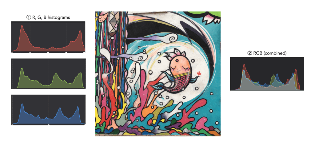
Consider the image example shown in Figure 1. This 3024×3024 pixel image has 9,144,576 pixels. On the left are the three individual RGB histograms, while on the right is the integral RGB histogram with the R, G, B, histograms overlapped. As I have mentioned before, there is very little information which can be gleaned by looking at the these two-dimensional RGB histograms – they do not really indicate how much red (R), green (G), or blue (B) there is in an image, because these three components can only be used together to produce information that is useful. This is because RGB is a coupled colour space where luminance and chrominance are coupled together. The combined RGB histogram is especially poor from an interpretation perspective, because it just muddles the information.
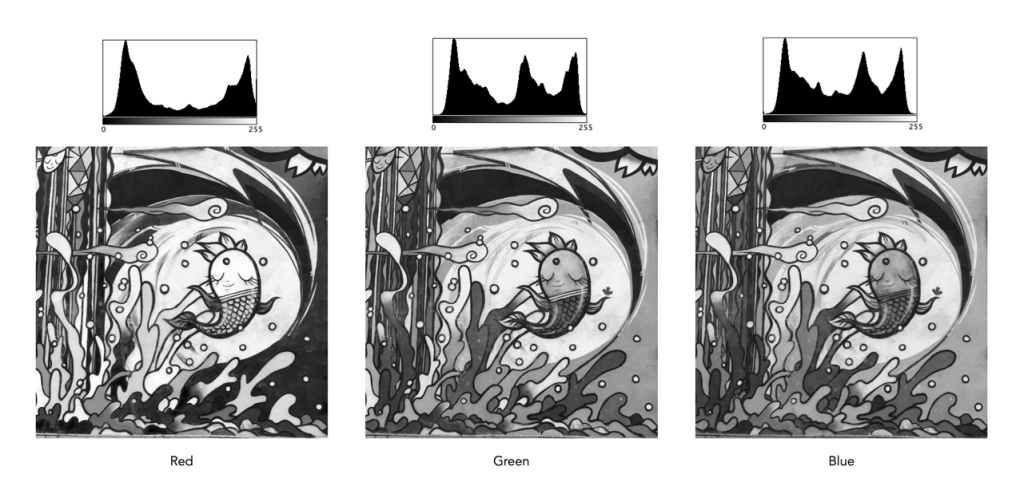
But to understand it better, we need to look at what information is contained in a colour image. An RGB colour image can be conceptualized as being composed of three layers: a red layer, a green layer, and a blue layer. Figure 2 shows the three layers of the image in Figure 1. Each layer represents the values associated with red, green, and blue. Each pixel in a colour image is therefore a set of triplet values: a red, a green, and a blue, or (R,G,B), which together form a colour. Each of the R, G, and B components is essentially an 8-bit (grayscale) image, then can be viewed in the form of a histogram (also shown in Figure 2 and nearly always falsely coloured with the appropriate red, green or blue colour).
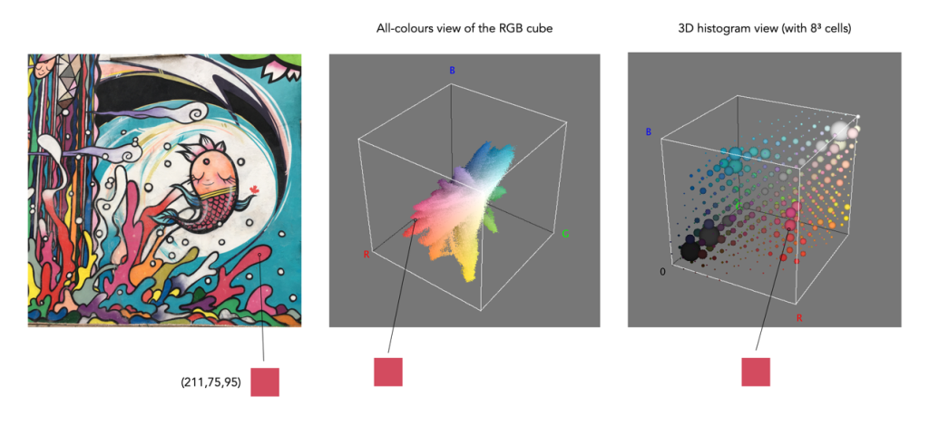
To understand a colour image further, we have to look at the RGB colour model, the method used in most image formats, e.g. JPEG. The RGB model can be visualized in the shape of a cube, formed using the R, G, and B data. Each pixel in an image has an (R, G, B) value which provides a coordinate in the 3D space of the cube (which contains 2563, or 16,777,216 colours). Figure 3 shows two different ways of viewing image colour in 3D. The first is an all-colours view of the colours. This basically just indicates all the colours contained in the image without frequency information. This gives an overall indication on how colours are distributed. In the case of the example image, there are 526,613 distinct colours. The second cube is a frequency-based 3D histogram, grouping like data together in “bins”, in this example the 3D histogram has 83 or 512 bins (which is honestly easier to digest than 16 million-odd bins). Within the image there is shown one pixel with the RGB value (211,75,95), and its location in the 3D histograms.
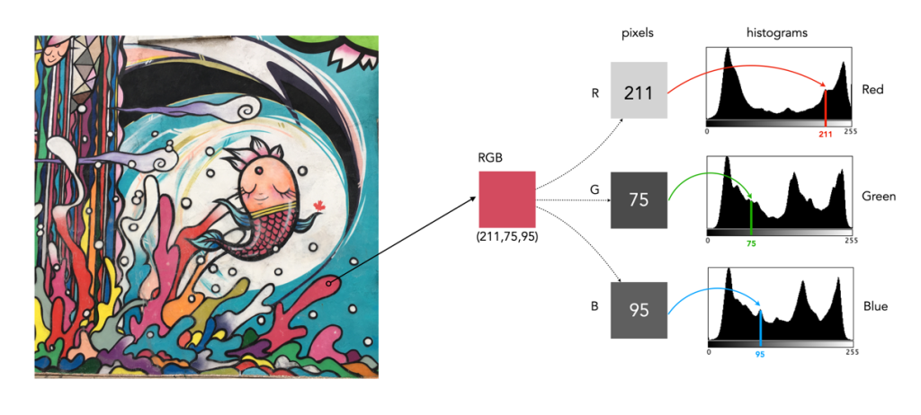
In either case, visually you can see the distribution of colours. The same can not be said of many of the 2D representations. Let’s look at how the colour information pans out in 2D form. The example image pixel in Figure 3 at location (2540,2228) has the RGB value (211,75,95). If we look at this pixel in the context of the red, green, and blue histograms it exists in different bins (Figure 4). There is no way that these 2D histograms provide anything in the way of context on the distribution of colours. All they do is show the distribution of red, green, and blue values, from 0 to 255. What the red histogram tells us is that at value 211 there are 49972 colour pixels in the image whose first value of the triplet (R) is 211. It may also tell us that the contribution of red in pixels appears to be constrained to the upper and lower bounds of the histogram (as shown by the two peaks). There is only one pure value of red, (255,0,0). Change the value from (211,75,95) to (211,75,195) and we get a purple colour.
The information in the three histograms is essentially decoupled, and does not provide a cohesive interpretation of colours in the image, for that you need a 3D image of sorts. Modifying one or more of the individual histograms will just lead to a colour shift in the image, which is fine if that is the what is to be achieved. Should you view the colour histograms on a camera viewscreen? I honestly wouldn’t bother. They are more useful in an image manipulation app, but not in the confines of a small screen – stick to the luminance histogram.